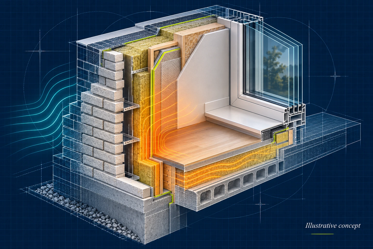
Illustrative concept — AI-generated artwork for this project overview.
Inside the interface
Software for building thermal tests
This project supported heat-retention testing in buildings. The software brought the operator's test settings, heater-controller readings, heat-flux measurements and external temperatures into a browser interface designed for use on a phone alongside the test equipment.
My work included the operator-facing web application and its integration with the embedded system. The interface separated test setup, live monitoring and log review, giving the operator a practical way to configure a run and follow the measurements as it progressed.
Setting up a heating and cooling test
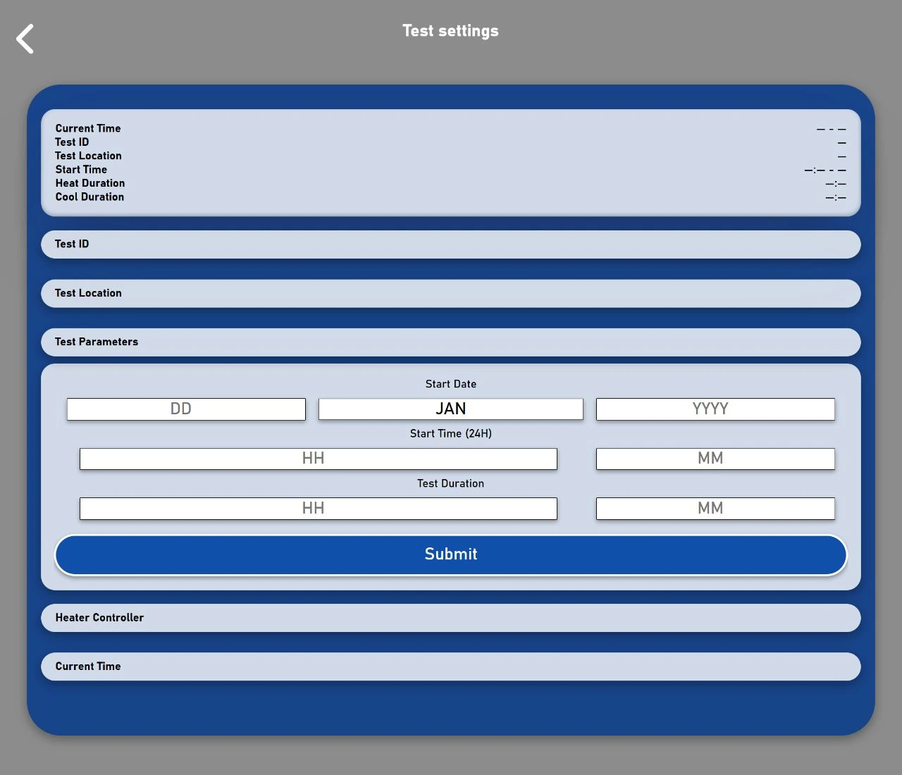
The test-settings flow exposed the start time, heating and cooling durations, heater temperature threshold and enable control. Operators could also set the system's date and time. The summary displayed the configured schedule alongside the controller clock so timing could be checked before a run.
JavaScript and jQuery submitted the timing and heater settings to the device's HTTP endpoints using AJAX. The interface showed confirmation when a request succeeded and refreshed the displayed values from the controller. The archived controller code also contains the scheduling logic and phase-event logging used by the heating and cooling workflow.
Live readings from the test equipment
The monitoring screen grouped measurements by device in expandable panels. It presented several kinds of equipment together:
- Heater controllers: two temperature readings and a power reading for each controller.
- Heat-flux modules: temperature, heat-flux and battery-voltage readings.
- External temperature sensors: ambient temperature and battery voltage.
The browser periodically requested the latest readings and updated the relevant values without reloading the page. Compact status indicators and collapsible sections helped keep the mobile interface usable while multiple modules were connected. The interface also included hardware-setup fields for module locations, heater wattages and heat-flux sensitivity.
A live log for reviewing each run
The results view displayed the incoming JSON log alongside system events, including changes between the heating and cooling phases. It refreshed while the results screen was open, and an optional auto-scroll control kept the newest entries in view.
Operators could download the log for review outside the application. A separate clear-log action required confirmation before sending the request. This provided both a readable monitoring screen during a test and access to the recorded data afterwards.
Connecting the browser to an embedded hub
The system operated over a local Wi-Fi network without requiring an internet connection. The archived hub implementation uses an ESP32 to serve web assets from a microSD card and expose HTTP endpoints for measurements and test settings.
On the device side, incoming serial messages were decoded as JSON and mapped to individual sensor and heater-controller readings. A real-time clock supplied timestamps, and received records were appended to the SD-card log. The web interface worked with this device-side data flow to make the readings and configuration available to the operator.
Implementation
The web application used HTML, CSS, JavaScript and jQuery, with AJAX requests for configuration and live updates. Its mobile layouts used grouped controls, expandable device panels and a dedicated log view. The embedded integration combined HTTP, serial communication and JSON, with an ESP32, a real-time clock and local SD-card storage.
The focus of this work was the software used to configure tests, observe the equipment and retrieve measurements for thermal analysis. It brought the web interface and physical test system together in a workflow that could be used beside the equipment.